Designing a Measurement System for Rowing: Boat Speed
It’s been a while since my last post about the upcoming rowing telemetry system that we’re working on, where I talked about the intricacies of measuring individual rower force or power production at the oar. We have actually been very busy building said system in the past few months and that’s why there was little time for blogging 🙂
Measurement of individual performance is very important when you want to get low-level data for improving individual performance or make decisions for crew selection. But most of the time when you’re working with a set crew, you want to work on improving boat speed. If you haven’t read it yet, I urge you to checkout Using Measurements in Rowing for an overview of the different levels of parameters we can measure in rowing and how we can apply them to improve performance. In fact speed is the most important metric in rowing, and when working with any kind of rowing performance measurement below the level of boat speed you should always keep an eye on boat speed.
In this post I want to look at the different ways we can measure boat speed.
Speed over Ground vs. Speed in Water
The interesting situation we’ve had in rowing until now though is that getting accurate stroke-by-stroke speed measurements has been surprisingly difficult. Most coaches today measure average speed over a fixed distance using landmarks and a stopwatch. However, not all rowers enjoy the benefit of rowing on a still standing body of water. On most rivers and streams, flow conditions that can change anytime make it very difficult to take comparable measurements.
It’s also not easy to take measurements on a body of water with flow and then subtract some kind of “flow speed” from the measurement to make them comparable. For example on rivers, the flow varies with the distance to the banks, depth of the river and any turns that the river takes. Leaving this issue aside, another problematic practice in use with some coaches is calculating the water’s flow speed by rowing a fixed distance over ground up- and downstream and divide it by the total time taken. While this is very simple, it’s plain wrong 🙂 If you’re interested to learn about this and other interesting effects (e.g. why it feels “harder” to row downstream than upstream) I want to refer you to Anu Dudhia from Oxford University, who has put together an excellent summary of the physics rowing on flowing water.
Measuring Speed in Water
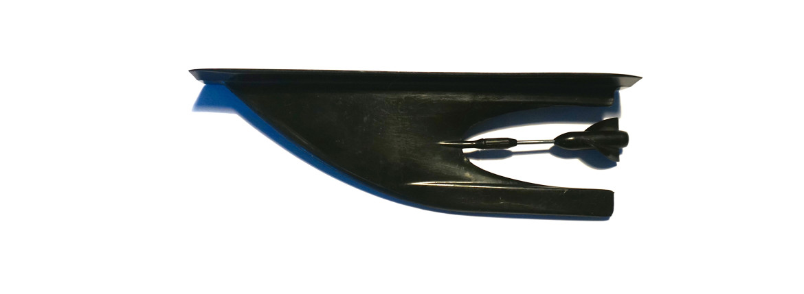
Alright, with that out of the way, let’s look at the ways we can actually measure true speed relative to the water. The most widely used systems in rowing today use an Impeller in the water. Impeller based systems work like a bike tachometer by counting the rotations of the impeller in the water. They require some sort of calibration value (i.e. the distance per rotation) and add additional drag on the shell. Besides requiring a careful installation (they need to be aligned to the centerline of the boat), they can quickly get stuck when there’s algae or some other sort of junk in the water. The upside is that they’re very simple devices and can be attached to any shell with some quality double sided tape.
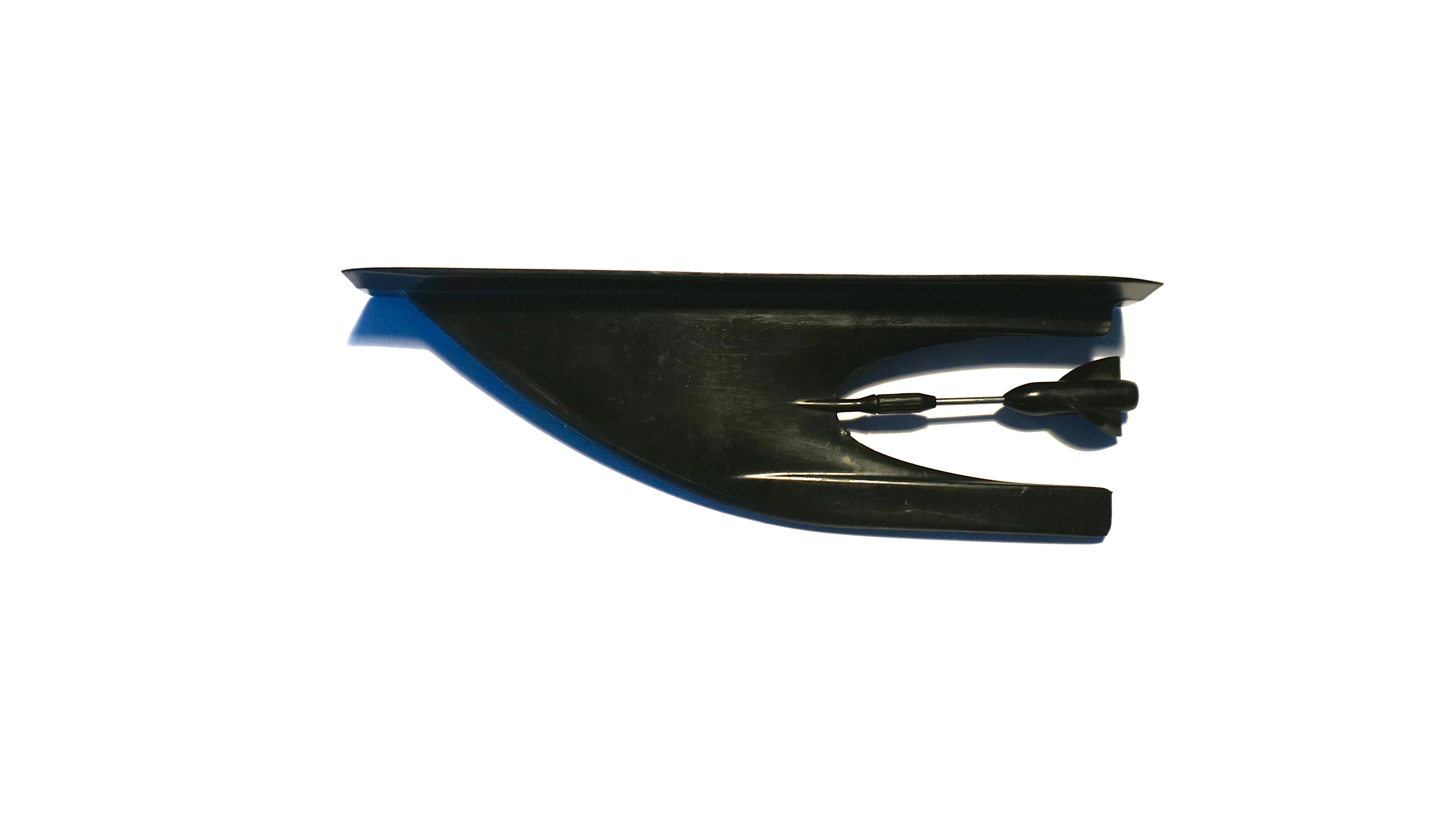
A typical Impeller that is mounted on the hull using double-side tape.
Another approach that has been used for in-water speed measurement in rowing uses the fact that water molecules are dipoles and respond to magnetic/inductive fields. These sensors however require a rather large surface area and thus usually need to be integrated with a fin or similar. This restricts their portability because the effort required to install them in a boat is rather significant.
A third approach would use doppler-shift based ultrasound measurements as is commonly used in maritime applications. These type of sensors are very expensive and require a lot of power (typically >50w) and are thus impractical for use in rowing.
A problem for all types of in-water speed sensors is that they can be affected by the turbulent flow close to the rowing shell. It is important that they measure the speed of the shell relative to the laminar flow, not the turbulent flow close to the shell surface.
In conclusion, impeller based measurements remain the most flexible and practical method for measuring speed in the water.
Measuring Speed over Ground
With the advent of satellite based global navigation systems such as GPS, measuring position and speed over ground has become practical in small footprint applications such as smartphones and mobile measurement systems. Common to all these systems is that they calculate a receivers’ position by taking measurements of time code signals sent by satellites in known orbits. Using those time codes, the receiver calculates the distance to each satellite and can calculate it’s own position.
Modern GPS Systems allow high rates of measurements (up to 10Hz) for location data and also can derive additional parameters such as position accuracy estimates as well as separate speed measurements based on carrier-wave doppler-shift. Even though GPS receivers are lightweight and require little power, the practical use of GPS for applications that require very accurate measurements in the order of 0.1m such as rowing is difficult because the systemic precision of GPS is in the order of 2m under perfect conditions. Accuracy and precision of GPS are very sensitive to signal quality and any obstructions in the line of sight to the GPS satellites in the orbits or even clouds and atmospheric turbulences have a significant negative effect.
Accuracy of Speed Measurements
I have made some simplifying assumptions in the previous paragraphs. Some of the sensors presented, e.g. the Impeller and GPS do not actually measure speed directly. An impeller measures rotations. When we now how many meters the boat travels per rotation, we can derive a speed measurement. The situation is similar for GPS based speed measurements, which accumulate the distance between locations and divide them by the time passed.
While these calculations are simple, we are effectively taking a distance measurement and create the derivate by time to obtain a speed measurement. Unfortunately, derivation greatly amplifies any noise in the measurements. Most GPS systems for example are only able to achieve a location precision of 2m under perfect conditions. This is a huge distance when compared to the speeds that we typically go at in rowing. Suppose we row a distance of 10m per stroke in 3 seconds, when our position measurements have a precision of 2m we can measure anything between 6 and 14m for that stroke. Another issue are the low sampling rates of GPS systems, which make it difficult to get a position measurement at exactly the time where the stroke starts and ends.
This is why most GPS based systems in use today use some sort of “smoothing” filter to smooth speed measurements over time or a fixed distance so that this measurement noise plays less of a role. Unfortunately, these filters make the system less responsive to changes in speed.
Impeller based measurements of instantaneous speed tend to be very noisy, especially at higher speeds where the layer of turbulent flow around the shell is larger. On the other hand, the average speed calculated for a full stroke is usually rather precise due to the high rotation frequencies of the impeller, but it’s accuracy is highly dependant on a good calibration value.
Working with Speed Measurements
Speed measurements should be available in different forms and presentations. For all these measurements, it is important that a user can decide whether the value shall be a measurement relative to ground or in water.
First, there’s instantaneous speed which shows how the boat speed changes over the stroke. Alongside with boat acceleration, this information gives a crew insight into the propulsion of the boat and helps spot any ‘defects’, like a premature slowing down of the boat in the recovery by pushing on the stretcher. Instantaneous speed must be measured at a high sample rate (e.g. 100Hz) and is best represented as a graph. In the below graph, the red line show instantaneous speed of the shell while the blue line shows the distance covered each stroke.
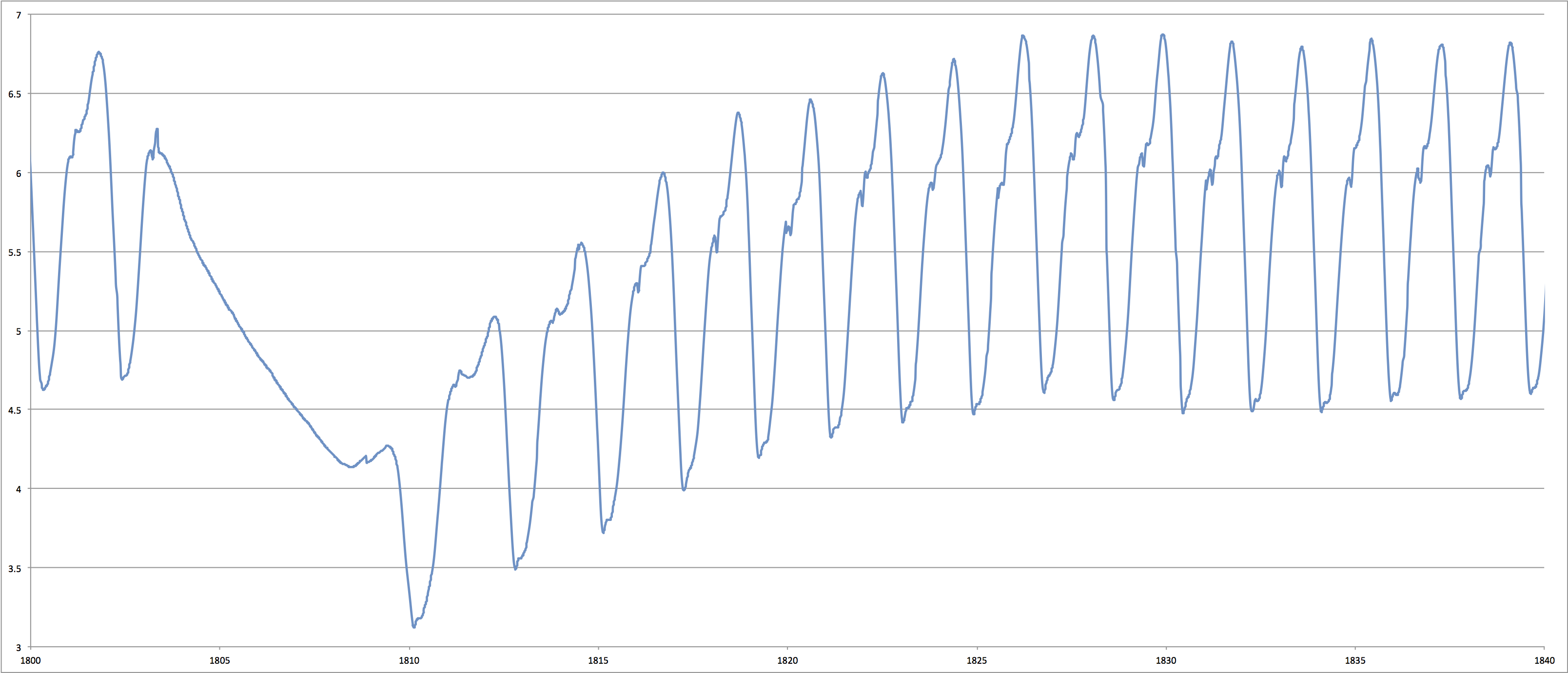
This graph shows instantaneous boat speed of a crew doing a short rest and then accelerating to strokerate 30. These measurements have been made with the Rowing in Motion Sensorbox.
Next, we’re interested in the stroke average speed of the boat for a single or multiple strokes. This can be represented in multiple equivalent numerical presentations like meters/second, projected pace/distance or putting it in relation to strokerate as meters/stroke.
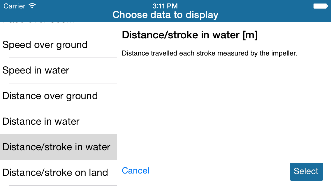
Selecting different speed and distance measurements for display in the Rowing in Motion App.
This instant feedback is very useful when working on improvements to rowing technique because it instantly shows any changes to boat speed that the athlete can associate with the performed motion sequence. For the athlete, it is a very similar experience to rowing on an ergometer that instantly calculates a speed for each stroke based on the applied force and performed work for that stroke.
Another way to calculate speed is as an average speed for a fixed timeframe or distance. Especially the later is useful for taking measurements that allow to predict race performance. This is a step that should also be available as a post-rowing analysis based on recorded data.
Implications for the Design of a Boat Speed Sensor
An ideal boat speed sensor should be able to measure boat speed and total distance over ground as well as speed and distance relative to the water that the shell is traveling in. For in-water speed measurements, the impeller currently represents the most feasible solution as it combines portability and reasonable effort for installation and practical use. A smart system that also features a GPS for speed and distance measurements over-ground can dramatically simplify the effort required for a reliable and correct calibration of the impeller.
While GPS today has become ubiquitous and consumer-grade chipsets (1-5Hz) built into most smartphones have become low-cost, the low sampling frequencies of and a systemic precision of larger than 2m under ideal conditions make it’s application for use in rowing challenging when an instant reaction to changes in boat speed is desired. It is easy to see that a 5Hz GPS receiver cannot supply the data required for e.g. measuring instantaneous speed at 100Hz, or even provide an accurate distance/stroke measurement due to the low sampling frequency and lack of required position accuracy.
We shall see in the next instalment of this series how the Rowing in Motion Sensorbox that we’re working on solves this challenge by combining the data from multiple different types of sensors with a high-quality professional 10Hz GPS solution and an optional impeller to achieve very accurate speed and distance measurements. See you next time!
Other posts in this Series:
- Using Measurements in Rowing – talks about what we can measure, why we should do so and what it means
- Designing a Measurement System for Rowing: The different levels of measurements in Rowing
- Designing a Measurement System for Rowing: Force and Power on the Oar
- Designing a Measurement System for Rowing: Boat Speed
- Designing a Measurement System for Rowing: Boat Acceleration and Movement
any update on the progress of the telemetry systems?